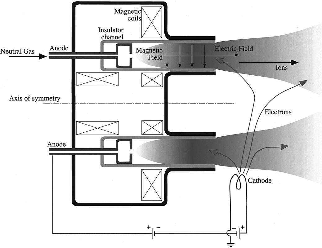
Figure 4: Cross section of a Hall Effect thruster with an extended insulator channel (Jahn & Choueiri, 2002).
Electrostatic Propulsion Systems
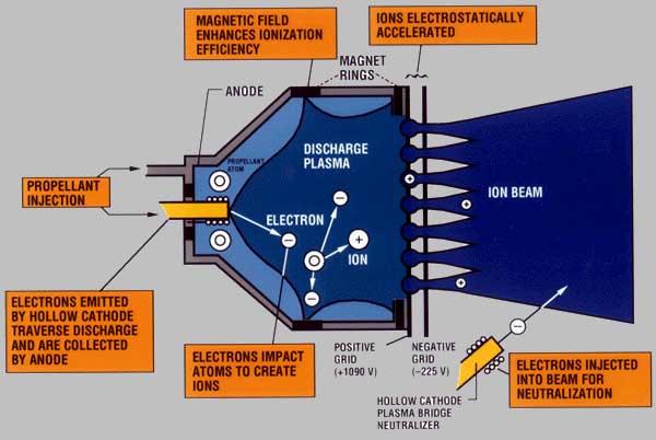
Figure 2: Alternate depiction of a gridded electrostatic ion thruster (Ward, 2000).
Electrostatic propulsion thrusters rely upon electric fields for accelerating and expelling ions to produce thrust and propel the spacecraft (European Space Agency, 2004). The production of ions for acceleration is achieved through several differing means, including the conventional electron bombardment method or the electron cyclotron resonance method, which electrically charges atoms from an onboard fuel supply (NASA, 2004). This fuel supply is an inert gas, often xenon or krypton, which is injected into the ionization chamber then expelled for propulsion (NASA, 2004). Electrostatic thrusters provide relatively large Isp values, ranging from 1,000 to approximately 10,000, and also have relatively high efficiencies ranging between 55% - 98% (Jordan, 2000). While electrostatic thrusters produce minimal thrust relative to alternative propulsion methods, the various implementations of this technology provide advantages not offered by other propulsion methods.
Gridded Electrostatic Ion Thruster
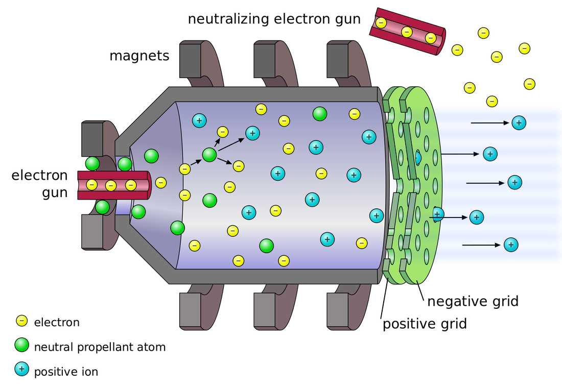
Gridded electrostatic ion thrusters, also called gridded electron ion bombardment thrusters, use the electron bombardment technique to produce ions from the inert injected gas (Jordan, 2000). As depicted in Figure 1, the electrons emitted from within the chamber collide with the inert gas (denoted a neutral propellant atom), and produce two electrons and a positive ion. Additionally, a magnetic field surrounding the collision chamber increases ionization efficiency (Ward, 2000), while the positive ions are accelerated through a positive and a negative charged grid to propel the spacecraft; the electrostatically charged grids have a large voltage discrepancy, creating a voltage inequality causing the positive ions to be expelled from the spacecraft (European Space Agency, 2004; Jordan, 2000). This stream of positive ions is then electrically neutralized by an external electron beam, as shown in Figure 2, which eliminates both the spacecraft’s accumulation of a net positive charge, possibly leading to damage, and prevents the internal potential of the ion stream from eliminating the generated thrust (European Space Agency, 2004). As shown in Table 1, this propulsion method provides an extremely high expected Isp, a relatively large maximum thrust level of .5 N, and a high efficiency rage between 80% - 95% (Jordan, 2000). However, structural instability and contamination risk detract from the overall viability of this propulsion system (Jordan, 2000). Overall, the combination of extensive testing and implementation, expansive opportunity for development, and inherent longevity of the ion bombardment propulsion system contribute to its operability and functionality in meeting the stated objectives of this paper.
Hall Effect Thruster
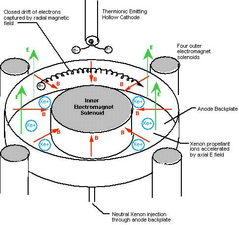
Figure 3: Depiction of the operation of a Hall Effect thruster (Edelman, 2012).
A second type of electrostatic propulsion system is the Hall Effect thruster. Considered as both electrostatic and electromagnetic propulsion systems (European Space Agency, 2004), Hall Effect thrusters contain both a radial magnetic field and an axial electric current, which interact to provide propulsion to the system (Jahn & Choueiri, 2002). As shown in Figure 3, an internal electromagnet is surrounded by several external electromagnets, with an internal propulsion chamber located between them, generating the radial magnetic field across said chamber (European Space Agency, 2004; Jordan, 2000). The disc-shaped internal chamber is closed on the propellant inlet side, while the opposite side is exposed for propellant ejection (European Space Agency, 2004). Several propellant feeds are located on the closed side, coupled with anodes that serve to generate the electric field necessary for propulsion; the inlets inject heavy gasses, typically xenon, into the internal chamber for ionization, acceleration, and expulsion (Jahn & Choueiri, 2002). A cross section of the Hall Effect thruster is depicted in Figure 4 showing the neutral gas feed into the thruster, the location and vector of the electric and magnetic fields, and the location of the electromagnets surrounding the propellant chamber. An anode, located at the neutral gas feed, assists in the generation of the electric field; accompanied by the external cathode on the opposite side, a flow of elections and a small amount of the propellant gas (approximately 5% of the total feed amount) originate from the cathode, which then travel to the plasma exhaust flow (European Space Agency, 2004; Jahn & Choueiri, 2002). Both the neutral gas and a percentage of electrons emitted by the cathode follow the plasma flow away from the thruster, and neutralize the charged stream; however, some electrons from the cathode traverse the thruster entrance and return to the internal propellant chamber (Prado, n.d.; European Space Agency, 2004). This electric current between the anode and cathode creates the electric field, while the aforementioned electromagnets create the magnetic field. From the combination of magnetic and electric fields arises the Hall Effect, the basic principle upon which the thruster operates; these two fields interact with the electrons in the internal propellant chamber, forcing them to move perpendicularly to both, and rotate radially around the central electromagnet (European Space Agency, 2004). This accumulation of electrons around a fixed location generates a negative net charge towards the end of the chamber, attracting the positive ions and expelling them for propulsion (European Space Agency, 2004). Drifting electrons, slowly escaping their radial rotation, interact with the neutral ions to produce two electrons and a positively charged ion, which then accelerates towards the large negative charge of the accumulated electrons (European Space Agency, 2004). To prevent electrical shorting with electrons interacting with the anode in large numbers, the radial magnetic field is within set parameters and variables (European Space Agency, 2004). While the above describes the basic operation of all Hall Effect propulsion systems, two different types of thrusters provide differing capabilities; the Stationary Plasma Thruster (SPT) and the Thruster with Anode Layer (TAL). The SPT type contains a longer acceleration zone for the charged ions, but exposure of the chamber walls to continual electron bombardment requires additional electron shielding (European Space Agency, 2004). However, in comparisons to the TAL, the SPT has markedly increased rates of corrosion, but has a more continuous variation in plasma potential within the electric field (European Space Agency, 2004). An example of the SPT is shown in Figure 5. The TAL’s anode is located closer to the radial magnetic field, and so has a shorter acceleration distance when compared to the SPT. However, this significantly decreases the corrosive effects of continual electron bombardment, but provides for a discontinuous jump in plasma potential due to the smaller distance between the magnetic field and the anode (European Space Agency, 2004). Additionally, the TAL system is depicted in Figure 6. Finally, the theoretical performance of Hall Effect thrusters, as noted in Table 1, is between 1,500 and 2,500 Isp and operates within 40% - 60% efficiency, indicating a relatively moderate to poor comparative performance with other electrostatic propulsion systems; yet, the Hall Effect thruster also has a relatively high projected thrust level of <220 mN, indicating a significant advantage over other electric propulsion systems (Jordan, 2000). In summation, the Hall Effect thruster system creates propulsion using magnetic and electric fields, for a moderate comparative performance in Isp and efficiency categories, but offers a relatively good thrust performance. This indicates the significant advantages and overall desirability of this thruster in terms of operational performance over other types of electrostatic thrusters.
Propulsion Systems Considered Currently Unviable
Several electrostatic propulsion technologies are deemed either underdeveloped or otherwise unviable for the objectives of this research paper and so are not to be fully analyzed; however, due to possible developments or extended research, they deserve partial consideration. The first of these technologies is the electrostatic colloid thruster. Relying upon a conductive liquid moving across a high potential, positive droplets form and are expelled from the spacecraft for propulsion (Jordan, 2000). Extremely small thrust capabilities, minimal efficiency, and insufficient development relegate the colloid thruster to the category of partial consideration (European Space Agency, 2004). Another technology not considered for full analysis is the Field Emission Electric Propulsion (FEEP) thruster. Similar to the colloid thruster in the implementation of a conductive liquid, this typically metal material is subjected to a strong magnetic field, which ionizes the surface of the liquid, contrasting with the colloid thruster which extracts charged droplets (Jordan, 2000). These ions are then propelled through a slit from the spacecraft, providing thrust. While extremely efficient with a high Isp, the FEEP system produces minimal thrust and is subject to contamination from the liquid metal, reducing its viability as a primary propulsion system for a high mass payload (European Space Agency, 2004). The final propulsion system not considered for full analysis is the Nano-Particle Field Extraction Thruster (NanoFET). Similar in basic principle to colloid and FEEP thrusters, the NanoFET expels charged particles through electric grids; however, the NanoFET system expels charged nanoparticles instead of either charged liquid droplets or ions (Liu, Keidar, Musinski, Gallimore, & Gilchrist, n.d.). The expulsion of nanoparticles provides several distinct advantages over other propulsion methods; primarily, thruster performance can be controlled based upon nanoparticle size, allowing for extensive scalability and large possible Isp ranges (Liu, Keidar, Musinski, Gallimore, & Gilchrist, n.d.). Two differing configurations are currently under investigation for use as a propulsion system; first, the liquid- reservoir system, in which the nanoparticles are stored, charged, and extracted for propulsion, and second, the dry-NanoFET system, which uses electric actuators to extract the charged particles for expulsion (Liu, et al., 2008). Promising initial results notwithstanding, the NanoFET system requires extensive testing and development before being fully considered as a viable propulsion method for high mass, long distance transportation.
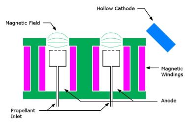
Figure 6: Cross section of a TAL Hall Effect thruster without an extended insulator channel (European Space Agency, 2004).
Electrostatic Propulsion Systems: Conclusion
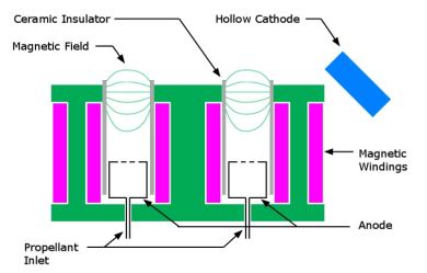
Figure 5: Cross section of an SPT Hall Effect thruster with an extended insulator channel (European Space Agency, 2004).
In meeting with the primary report objectives, several electrostatic propulsion types offered significant advantages over comparative systems. The NanoFET system, while highly promising and offering massive operational advantages over other electrostatic systems, is not included due to a stage of insignificant development. The other two primary propulsion systems were the Hall Effect thruster and the gridded electrostatic ion thruster; offering significantly higher efficiencies and a larger Isp range, the gridded electrostatic ion thruster system fails to fully meet the outlined objectives due to an extremely low thrust performance. The Hall Effect thruster, while having only moderate Isp and efficiency levels, more adequately meets the requirements for a long distance, high mass transport system. Therefore, the Hall Effect thruster is recommended as the most viable electrostatic propulsion system, with the NanoFET propulsion system as a possibly viable option, pending development.
